The determination of the downwind box geometry is carried out through three sequential operations, as described on page 16575 of
We start with a smaller rectangular mask of dimension (length x breadth) 0.4 x 0.2° placed at the source in the downwind direction inferred from boundary layer average ERA5 meteorology to define the area containing the plume (Figure S1). Next, we rotate this mask from -40 to +40° at 5° intervals around the inferred ERA5 wind direction such that the average XCH4 enhancement in the rectangular mask is maximal. After we set the new wind direction, the length of the rectangular mask in the downwind direction (along the x-axis) is varied to define the end of the plume. This end is fixed by incrementing the length of the rectangular mask by 0.1° intervals until the difference between enhancement of two consecutive increments is less than 5 ppb. Similarly, the width of the rectangular mask (along the y-axis) was fixed by incrementing the width in the lateral direction of the plume at an interval of 0.05° until the incremental change in enhancement is less than 5 ppb.
The determination of the downwind box geometry depends on how enhancement is defined, which is not uniquely prescribed. One possible interpretation defines enhancement as the difference between the observed field and the estimated background, with all pixels exhibiting zero or negative differences masked out. Under this definition, enhancement values are strictly non-negative.
An alternative interpretation defines enhancement simply as the difference between the observed field and the background concentration, without masking negative values. Under this definition, enhancement values may be negative and are retained in subsequent calculations. In the context of atmospheric dispersion, negative values typically represent net removal through absorption. Such processes are outside the scope of this analysis and are assumed to be negligible over the timescale relevant to plume evolution.
To illustrate this issue, consider Figure 7 below. The left panel shows the behaviour of the algorithm when no masking is applied to the enhancement field. Brown pixels represent the true plume, characterised by a uniform enhancement of 10
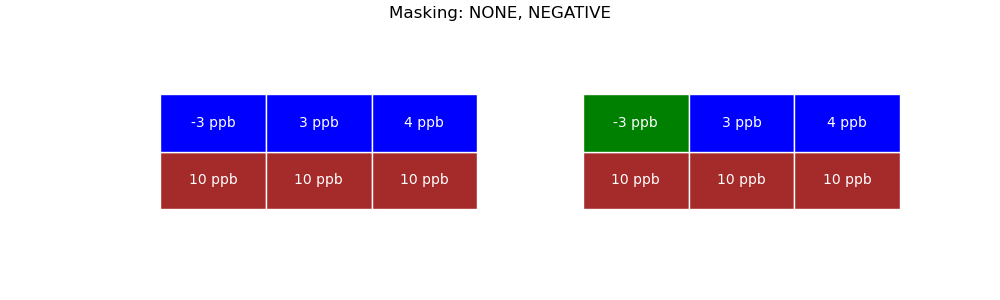
In the left panel, no masking is applied. The incremental change in mean enhancement resulting from the proposed box expansion is 4
In the right panel, the pixel with a negative enhancement -3
Below, we discuss the outcomes of each of the three downwind box adjustment operations separately.
Adjustment of downwind box direction
A rectangular box with dimensions 0.4° × 0.2° was applied to the image, and the mean enhancement was computed for box rotations spanning -40° to +40°. The maximum average enhancement of 5.83
| Rotation | Azimuth | Box Average Enhancement |
|---|---|---|
| -40 | 219.362 | -1.762 |
| -35 | 224.362 | 0.793 |
| -30 | 229.362 | 1.064 |
| -25 | 234.362 | 1.523 |
| -20 | 239.362 | 2.025 |
| -15 | 244.362 | 4.008 |
| -10 | 249.362 | 4.728 |
| -5 | 254.362 | 5.198 |
| 0 | 259.362 | 3.987 |
| 5 | 264.362 | 5.832 |
| 10 | 269.362 | 5.320 |
| 15 | 274.362 | 3.806 |
| 20 | 279.362 | 1.463 |
| 25 | 284.362 | -0.524 |
| 30 | 289.362 | -0.655 |
| 35 | 294.362 | -1.158 |
| 40 | 299.362 | -0.641 |
Adjustment of downwind box length
The purpose of this step is to extend the downwind box length until the incremental increase in mean enhancement becomes negligible. Specifically, the box is lengthened iteratively until the increase in average enhancement falls below a predefined threshold of 5
| Box length | Enhancement | Increment |
|---|---|---|
| 44000.0 | 75.812 | NaN |
| 55000.0 | 125.428 | 49.616 |
| 66000.0 | 188.667 | 63.239 |
| 77000.0 | 232.556 | 43.889 |
| 88000.0 | 326.990 | 94.434 |
| 99000.0 | 362.093 | 35.104 |
| 110000.0 | 332.218 | -29.875 |
Adjustment of downwind box width
The width adjustment is performed in the same manner as the length adjustment, incrementally expanding the box width until the increase in average enhancement falls below the prescribed threshold. In this case, the procedure terminates at a box half-width of 27.5
| Box half-width | Enhancement | Increment |
|---|---|---|
| 11000.0 | 362.093 | NaN |
| 16500.0 | 390.265 | 28.171 |
| 22000.0 | 403.950 | 13.685 |
| 27500.0 | 361.749 | -42.201 |
Main constructs
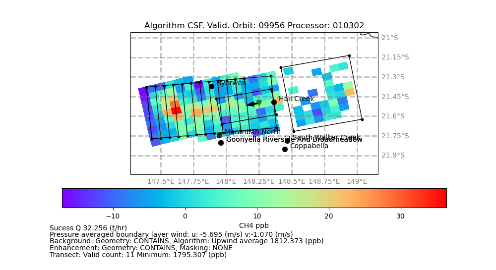
The key elements constructed by the algorithm are illustrated in Figure 8 below.